1. Brief Introduction
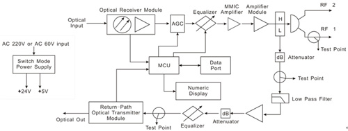
This optical node is built with high quality Silicon optical receiver module to complete O/E conversion. The forward-path RF amplification is carried out in two stages: The first stage by a GaAs MMIC amplifier, and the second stage by a GaAs power doubler amplifier module. GaAs technology ensures good RF specifications.
Micro Control Unit (MCU) is employed on this node. It senses working parameters (Such as optical power, RF out level, DC voltage, temperature, etc.) and gets them shown on the 4-digit numeric display, making configuration and maintenance simple and easy.
Thanks to the MCU, unlike other nodes using plug-in equalizer/attenuator to control slope/gain, the forward-path’s slope and gain could be electronically tuned through buttons below the numeric display.
Optical AGC is another noticeable feature. RF output level remains constant when optical input power varies within -7~+1dBm. AGC range could be electronically tuned through buttons below the numeric display.
2. Product Features
- High quality Silicon optical receiver module completes O/E conversion.
- Two-Stage RF amplification design: The first stage by a GaAs MMIC amplifier, and the second stage by a GaAs power doubler amplifier module.
- Optical AGC function keeps RF output level constant when input optical power varies.
- Dual RF outputs. RF output level ≥104dBμV.
- MCU senses node’s working parameters and get them shown on the numeric display. MCU also enables operation buttons below numeric display to tune forward-path RF slope, level, and AGC range.
- All configured parameters could be automatically loaded when node is restarted.
- RF test point is built for both forward-path and return-path.
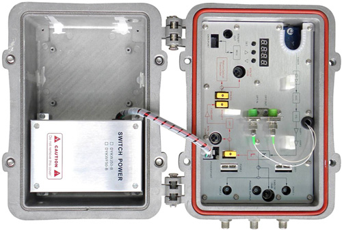
- Waterproof Aluminum die-casting housing prevents humidity and electromagnetic interference.
- Suitable for outdoor installation where requests strand mounting.
3. Block Diagram
4. Technical Specifications
Forward-Path |
Unit |
Specifications |
Optical |
Wavelength |
nm |
1290~1580 |
Input Power |
dBm |
-7~+1 |
Optical AGC Range |
dBm |
-7~+1 |
Connector |
/ |
SC/APC or FC/APC |
RF |
Frequency |
MHz |
47/54/87~862 |
Output Level |
dBμV |
≥104, (2 equal RF out, optical input @ -1dBm) |
Connector |
/ |
F-female |
Return Loss |
dB |
≥14 |
Test Point |
dB |
-20±2 |
Optical Link Performance |
Frequency Response |
dB |
±1.5 |
C/N |
dB |
≥51 |
C/CSO |
dB |
≥63 |
C/CTB |
dB |
≥65 |
Test Conditions: 59-CH PAL-D analog signal, 1310nm optical transmitter GFS1310F-B, node with -1dBm optical input power and 10dB equalization. |
Return Path (Optional) |
Unit |
Specifications |
RF |
Frequency |
MHz |
5~30/42/65 |
Input Level |
dBμV |
75 |
Return Loss |
dB |
≥14 |
Test Point |
dB |
-20±2 |
Optical |
Wavelength |
nm |
1310±20 |
Laser Type |
/ |
FP Laser or DFB Laser |
Transmitting Power |
mW |
1~2 (Depends on Laser) |
TX Power Stability |
dBm |
±0.5 |
NPR Dynamic Range
(NPR≥30dB) |
dB |
≥15dB, FP Laser. |
Optical Link Frequency Response |
dB |
±1 |
Power Supply |
Unit |
Specifications |
Power Supply |
V |
AC 60V or AC 220V |
Power Pass Current |
A |
10 |
5. Numeric Display and Control Buttons
The numeric display and control buttons are shown as below.
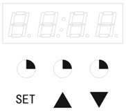
The numeric display has 4 digits. From left to right, the first one digit or two digits indicate which parameter is being shown, and other digits indicate the parameter’s value.
Button “SET” functions like SKIP. Numeric display would show next parameter when “SET” is pushed.
▲ / could be used only when the parameter shown on the display is configurable. ▲ is used to increase a parameter, and button is used to decrease a parameter. The table below lists out what parameters can be shown on the display and which could be modified.
Number shown by 1st
one digit or two digits |
Specification Name |
Unit |
Flashing |
Configurable |
1 |
Forward-Path optical power |
dBm |
Yes |
No |
2 |
Forward-Path RF out level |
dBμV |
Yes |
No |
3 |
Return-Path optical power |
dBm |
Yes |
No |
4 |
Temperature |
°C |
Yes |
No |
5 |
5V Voltage |
V |
Yes |
No |
6 |
24V Voltage |
V |
Yes |
No |
E |
Forward-path Equalization
(Slope Control) |
dB |
No |
Yes |
A0: |
Forward-path Attenuation
(Gain Control) |
dB |
No |
Yes |
A1: |
AGC Range |
dBm |
No |
Yes |
For example,

The first digit “1” represents forward-path optical power. “-1.9” means the forward-path optical power is -1.9dBm
|