■
Optical Node GWS862H2J(F)-K
|
| Brief Introduction
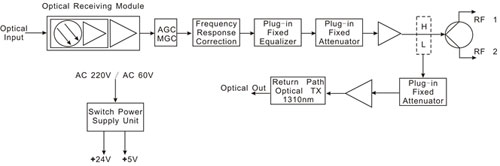
The most noticeable feature of GWS862H2J-K / GWS862H2F-K is the optical AGC function. Under AGC working mode, the AGC circuit senses input optical power and keeps output RF level constant when input optical power varies within -5~+2dBm.
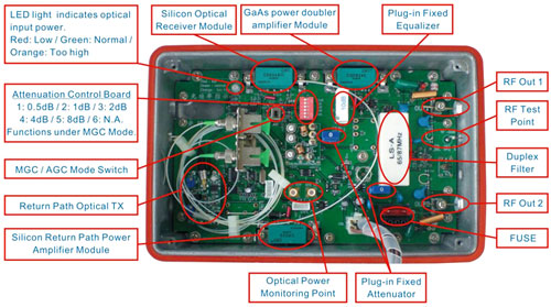
Another unique feature is the Attenuation Control Board which works under MGC mode. The Board provides attenuation choices from 0dB to 15.5dB. The control is as precise as 0.5dB/step.
The O/E conversion of this node is carried out by high quality Silicon optical receiver module which is embedded with IC amplifier. The allowable optical input power is as wide as -9~+2dBm.
Forward-path RF amplification is done by a GaAs power doubler amplifier module. A plug-in fixed value equalizer is built to regulate output RF’s slope and a plug-in fixed attenuator to tune RF level down. 2 RF outputs is provided by this node.
Bidirectional design provides optional return-path. The node could be made with or without return path. For those without return path, upgrade to bidirectional could be made at spot by adding return-path transmitter module and necessary accessories. A plug-in fixed value attenuator is built to tune laser’s input RF level.
Product Features
- High quality Silicon optical receiver module embedded with IC amplifier.
- 1290~1580nm optical wavelength, -9~+2dB allowable optical input power.
- AGC working mode or MGC working. A switch is embedded.
- Built with AGC circuit to sense optical input power and keep output RF level constant (under AGC mode).
- Built with unique Attenuation Control Board to tune forward-path RF level (under MGC mode).
- GaAs power doubler amplifier module enlarges RF level.
- 2 RF outputs, level ≥104dBμV when optical input power as -1dBm.
- Forward-path RF slope is regulated by plug-in fixed value equalizer, and level could be tuned down with plug-in fixed value attenuator.
- Bidirectional design. Return-path is optional.
- Duplex filters 30/47MHz, 42/54MHz, and 65/87MHz optional.
- Optical power measuring point is built for both forward-path and return-path.
- Tri-Color LED at optical input indicates optical power status.
- RF Test Point is built for both forward-path and return-path.
- Independent power supply port. RF output ports could feed power into coaxial cables.
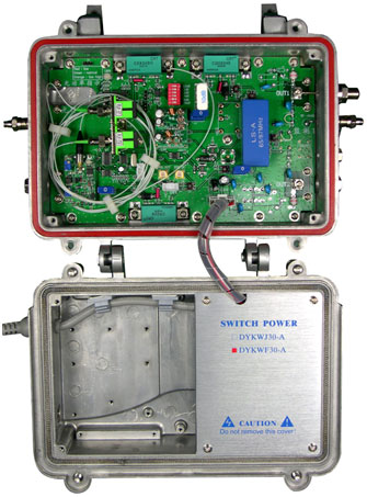
- Waterproof metal die-casting housing.
- Suitable for strand mounting.
Block Diagram
Technical Specifications
Forward path |
Unit |
Specifications |
Optical |
|
|
Wavelength |
nm |
1290 ~ 1580 |
Allowable Input Power |
dBm |
-9 ~ +2 |
Return Loss |
dB |
≥45 |
Optical AGC Range |
dBm |
-5 ~ +2
(Keeps RF output level constant when -5~+2dBm input) |
Connector |
- |
SC/APC or FC/APC |
RF |
|
|
Frequency |
MHz |
47/54/87~862, specify when order. |
Number of Outputs |
- |
2 equal outputs |
Output Level |
dBμV |
≥104dBμV (optical input power as -1dBm) |
In-Band Flatness |
dB |
±0.75 |
Return Loss |
dB |
≥16dB(47~550MHz)
≥14dB(550~1000MHz) |
Test Point |
dB |
-20 ±2 |
Optical Link Performance |
|
|
C/N |
dB |
≥51 |
C/CSO |
dB |
≥63 |
C/CTB |
dB |
≥65 |
Test Conditions: 59-CH PAL-D mixed with 200MHz wide QAM digital signal, 10km optical fiber, node with -1dBm optical input power and 10dB equalizer. |
Return Path |
|
|
Optical |
|
|
Wavelength |
nm |
1310 ±20 |
Laser Type |
- |
FP Laser |
Transmitting Power |
mW |
1~2 |
NPR Dynamic Range
(NPR≥30dB) |
dB |
≥15 |
RF |
|
|
Frequency |
MHz |
5~30/42/65 |
Input Level |
dBμV |
75 ±5 |
Return Loss |
dB |
≥16 |
Power Supply |
|
|
Power Supply |
V |
AC 60V or AC ~220V |
Power Pass |
A |
10 |
Environmental |
|
|
Working Temperature |
°C |
-25 ~ +55 |
Storage Temperature |
°C |
-40 ~ +80 |
Relative Humidity |
- |
≤85% |
Mechanical |
|
|
Dimensions |
mm |
276(L)×215(W)×113(H) |
Weight |
kg |
2.5 |
Attenuation Control Board for MGC Mode |
Switch Number |
Attenuation dB |
1 |
0.5 dB |
2 |
1.0 dB |
3 |
2.0 dB |
4 |
4.0 dB |
5 |
8.0 dB |
6 |
N.A. |
Different combination of switches provides different attenuation. |
|